- Home
- Products
- Ross Asia 77 series double valve Safety cat. 4 PL e, internal monitoring, automatic reset
Japan, Ross Asia
Ross Asia 77 series double valve Safety cat. 4 PL e, internal monitoring, automatic reset
Made in Japan
Manufacturer : Ross Asia
Model : 77 series double valve
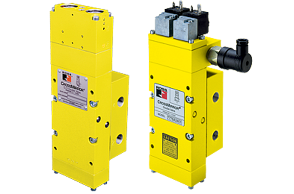
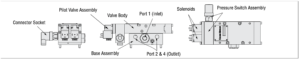
Control Reliable C roSS Mirror ® Double Valves 77 Series Product Overview
Safe Return Safety Function
This valve is constructed with precision, stainless steel spools as the main valve elements, and is designed to offer added safety to the operation of many pneumatically controlled machines such as small size pneumatic cylinder-operated presses, valve operators, and safety latches.

Solenoid Pilot Controlled
»Status indication switch (ready-to-run) to inform machine controller of valve condition
Pressure Controlled for 2-Hand Control Applications
» Requires two inputs within 500 ms
» Senses asynchronous inputs via status indicator switch
» Asynchronous inputs result in a fault condition where pressure is applied to port 2
» Status indication switch available to be integrated with electrical safety control system where equipped
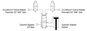
The pressure controlled valve is a two hand pressure controlled 4-way double valve controlled by two separate pneumatic signals essentially providing “AND” gate control for the output ports. Both pilot signals must be provided within approximately 500 milliseconds of each other to actuate the valve.
Proper actuation shifts output pressure to port 4. If the valve is not actuated, not provided appropriate pneumatic signals within the discordance window or if the valve actuates abnormally, inlet pressure will only be passed to port 2 – cylinder retracted.
Features

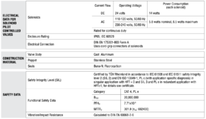
PRODUCT CREDENTIALS

Specifications

Ordering Information
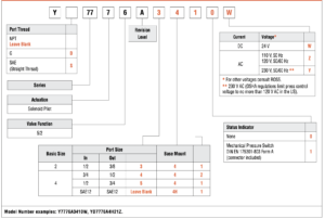
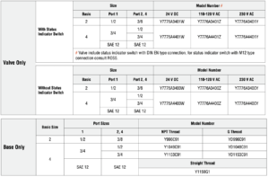
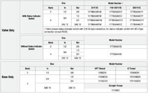
5/2 SOLENOID PILOT CONTROLLED VALVES – VALVE AND BASE
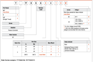
MODEL NUMBER CONFIGURATOR(4-Way 2-Position Valves)
5/2 Solenoid Pilot Controlled Valves – Valve only, Base only
| Solenoid & Pressure Switch Pinouts | |
| Solenoid | DIN EN 175301-803 Form A |
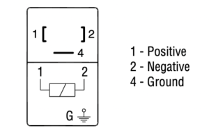 | |
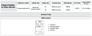
Pressure Switch for Status Indicator | ROSS Connector |
 | |
Valve Operation
| SOLENOID PILOT CONTROLLED VALVES | |
| Normal Operation | After installation the valve is operated by energizing both solenoid pilots (S1 and S2) simultaneously. This causes both main valve elements to be actuated so that air from inlet port 1 flows to outlet port 4. Air downstream of port 2 is exhausted through port 3. When the solenoid pilots are de-energizing, both valve elements are de-actuated, and air then flows from inlet port 1 to outlet port 2. Air downstream of port 4 is exhausted through port 5 |
| Safety Function | If the two main valve elements are not actuated or de-actuated synchronously, within 500 ms, the valve defaults so that outlet port 2 receives full inlet pressure, and outlet port 4 is exhausted through port 5. If this abnormal operation is the result of a temporary circumstance, the valve will be ready to resume normal operation as soon as both pilot signal ports have been de-energized and both main valve elements have returned to their normal ready-to-run position. Applying the electrical signal to both solenoids simultaneously will resume normal operation. If the cause of the abnormal operation is still present, the valve will either remain in the default position (pressure on port 2 and not port 4) or will again go into this position on the next actuation attempt. The source of the abnormality must be investigated and corrected before further operation. |
| Pressure Switch | Valves with model numbers ending in the number 1 have a pressure switch to provide user feedback when movement of the main valve elements was asynchronous. |
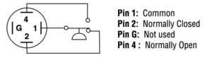
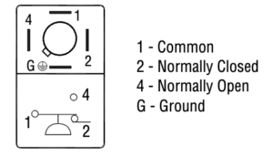
Terminals 1 and 4 are connected when air pressure is present and the valve is “Ready-to-Run”. If an abnormal operation has occurred or pressure is removed from the valve inlet, terminals 1 and 2 are connected.
Note: DC voltage pressure switches do not have a ground terminal.
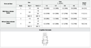
| Valve Schematic | |
 |
Valve Technical Data
Solenoid Pilot Controlled Valves – Valve and Base Assembly with Remote Reset
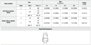
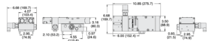
| Dimensions-Inches(mm) | |
| Basic Size 2 | with Status Indicator Switch |
 | |
| without Status Indicator Switch | |
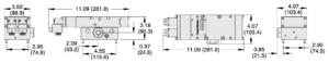 | |
| Basic Size 4 | with Status Indicator Switch |
 | |
| without Status Indicator Switch | |
 | |
Ordering Information
5/2 PRESSURE CONTROLLED VALVES – VALVE AND BASE
MODEL NUMBER CONFIGURATOR(4-Way 2-Position Valves)
5/2 Pressure Controlled Valves – Valve only, Base only
| Pressure Switch Pinout | |
Pressure Switch for Status Indicator | ROSS Connector |
 | |
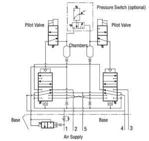
| Typical 2-Hand-Anti-Tie-Down Application | |
 |
Valve Operation
| PRESSURE CONTROLLED VALVES | |
| Normal Operation | After installation the valve is operated by pressurizing both pilot supply ports (S1 and S2) simultaneously. This causes both main valve elements to be actuated so that air from inlet port 1 flows to outlet port 4. Air downstream of port 2 is exhausted through port 3. When the pilot supply ports are de-pressurized, both valve elements are de-actuated, and air then flows from inlet port 1 to outlet port 2. Air downstream of port 4 is exhausted through port 5. |
| Safety Function | If the two main valve elements are not actuated or de-actuated synchronously, within 500 ms, the valve defaults so that outlet port 2 receives full inlet pressure, and outlet port 4 is exhausted through port 5. If this abnormal operation is the result of a temporary circumstance, the valve will be ready to resume normal operation as soon as both pilot signal ports have been de-pressurized and both main valve elements have returned to their normal ready-to-run position. Applying pressure to both signal ports simultaneously will resume normal operation. If the cause of the abnormal operation is still present, the valve will either remain in the default position (pressure on port 2 and not port 4) or will again go into this position on the next actuation attempt. The source of the abnormality must be investigated and corrected before further operation. |
| Pressure Switch | Valves with model numbers ending in the number 1 have a pressure switch to provide user feedback when movement of the main valve elements was asynchronous. |
Terminals 1 and 4 are connected when air pressure is present and the valve is “Ready-to-Run”. If an abnormal operation has occurred or pressure is removed from the valve inlet, terminals 1 and 2 are connected.
Note: DC voltage pressure switches do not have a ground terminal.

| Valve Schematic | |
 |
Valve Technical Data
Pressure Controlled Valves – Valve and Base Assembly with Remote Reset
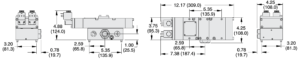
| Dimensions-Inches(mm) | |
| Basic Size 2 | with Status Indicator Switch |
 | |
| without Status Indicator Switch | |
 | |
| Basic Size 4 | with Status Indicator Switch |
 | |
| without Status Indicator Switch | |
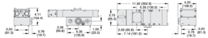 | |

Accessories
ELECTRICAL STATUS INDICATION
PREWIRED ELECTRICAL CONNECTORS
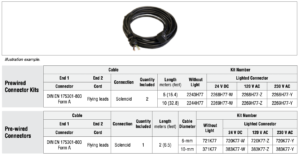
ELECTRICAL CONNECTORS

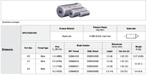
EXHAUST SILENCERS
Related Products
-
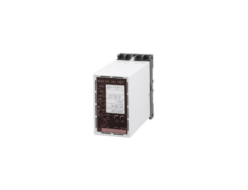
Watanabe WAP-MSW 2 output potentiometer converter – Signal Converter
-
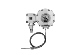
NAGANO KEIKI TD__ Liquid or gas filled temrmometer
-
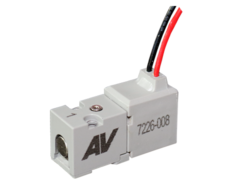
Ross Asia M10 series Inline spool valve
-
Murakoshi MY-60X Three-dimensional Trademark Dust Collector
-
Kanetec KETV-3060F Electromagnetic Chuck With Vacuum Chuck Function
-
Nippon Chemical Screw PPS/SH(M-L) PPS/Extremely low head bolt with hexalobular hole
REQUEST QUOTATION

PAYMENT

LINK


