Japan, Ross Asia
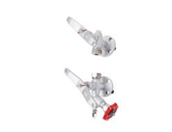
Ross Asia CC4 series double valve Safety cat. 4 PL e, external monitoring

Made in Japan
Manufacturer : Ross Asia
Model : CC4 series double valve
Control Reliable Double Valves Cross Check TMCC4 Series Product Overview
Safe Control and Load Holding Safety Function
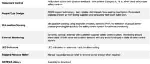
The CC4 Series valve safety function is of safe cylinder control, safe cylinder stop, and/or load-holding. This function is accomplished by blocking further supply of pneumatic energy through the valve and blocking the exhaust of any pneumatic energy from the cylinder lines and cylinder downstream of the valve whenever the valve is shut off or a fault occurs within the valve.

The CC4 Series double valve is a 4/3 safety directional valve, closed center, designed to control the direction of air flow into and out of a double-acting cylinder or other pneumatic actuator in order to drive the cylinder forward or backward to suit the requirements of the machine operation until signaled to shut off and trap pneumatic energy in the cylinder in order to stop cylinder motion (load holding). Thus, reducing the potential hazard of unexpected cylinder motion during employee access for production-related tasks and/or minor servicing. Turning off all solenoids on the 4/3 CC4 Series valve returns the valve to the center position in order to stop cylinder motion – this also allows jogging of the cylinder.
The CC4 Series valve offers this function with the required level of control expected of the machine’s (system’s} safety control system up to Category 4, PL e. Such a control system must be capable of inhibiting further operation of the valve in the event of a fault within the valve.
VALVE FEATURES
PRODUCT CREDENTIALS

Specifications

Ordering Information
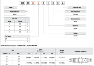
MODEL NUMBER CONFIGURATOR(4-Way 3-Position Valves)
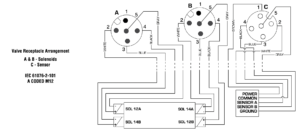
| Valve Wiring Diagram | |
 |
Valve Technical Data
| Dimensions-Inches(mm) | |
| Port Size 1/4 & 3/8 |  |
| Port Size 1/2 & 3/4 |  |

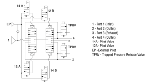
| Valve Schematic | |
 |
Valve Operation
| Conditions at Start | Pressure applied to port 1, but all solenoids off. All ports (1, 2, 3, & 4) are blocked. |
 | |
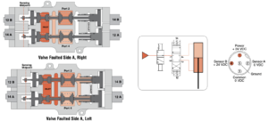
| Normal Operation | Energizing both solenoids 14A & 14B causes the valve to shift and supply pressure to port 4 while exhausting pressure from port 2, thus, extending the cylinder. Conversely, energizing solenoids 12A & 12B causes the valve to shift and supply pressure to port 2 while exhausting pressure from port 4, thus, causing the cylinder to retract. Turning all the solenoids off allows the strong return springs to shift the redundant valves back to the center position, which blocks all ports. This traps any downstream pressure in the cylinder and holds it in its current position (see below on the right, image of valve de-energized trapping pressure). Each of the mid-position feedback sensors provide a voltage output when the valve is in the center, safe position, but no voltage output when the valve internals are shifted out of the center position. This provides a detectable center position for both sets of valve internals. NOTE: Momentary operation of either the 12A & 12B solenoids (or 14A & 14B solenoids) can be utilized to jog the cylinder to intermediate positions instead of just fully extended or fully retracted. This is sometimes referred to as “inching.” |
 | |
| Monitoring | External monitoring of the Cross CheCk TM mid-position sensors must be performed by an external monitoring system. Such a monitoring system must be capable of inhibiting the operation of the valve. The safety control system must de-energize the valve’s solenoids in the event of a fault within the valve and/or within the safety control system, and check for achievement of the valve center position before allowing an attempt to re-energize the valve. Valve reset is accomplished by de-energizing all of the valve’s solenoids. Reset of the safety control system should not occur unless the valve has fully returned to its center position (both sets of internals). The output voltage of the sensors, when switched on (center position), equals approximately the voltage supplied to the sensors by the safety controller. For example, 24 volts DC In = 24 volts DC Out, etc. |
| Abnormal Operation | When energizing, if both sets of valve internals do not shift synchronously (either on or off), the Cross Check TM valve will block all ports. While in this fault condition, the valve cannot further pressurize or exhaust the cylinder lines. Also, as long as the fault condition exists, there will be a voltage output from the valve internals that did not shift from center, but there will not be an output from the other valve internals that did shift off center. This provides a detectable fault condition as both sensors need to agree in order to not indicate a fault. |
 | |
 | |
| Trapped Pressure Release | In order to perform machine maintenance, after stopping the machine and performing lockout/tagout, pressure trapped in the cylinder by the Cross Check TM valve can be released (exhausted) by the two manually-operated 2 way valves that are provided in the Cross Check TM valve sub-base – one each per valve outlet port. This provides a way to slowly lower the cylinder to its lowest position. NOTE: Operating the manual trapped pressure release valves will cause movement of the cylinder. Use caution to avoid any hazards associated with this movement. |
 |
Accessories
PREWIRED ELECTRICAL CONNECTORS

EXHAUST SILENCERS


