- Home
- Products
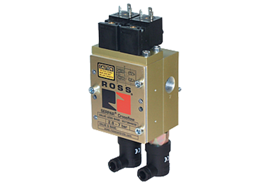
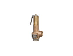
- Ross Asia Crossflow 35 series Double valve, with or without pressure switch, ports 1/4 to 3/4
Japan, Ross Asia
Ross Asia Crossflow 35 series Double valve, with or without pressure switch, ports 1/4 to 3/4
Made in Japan
Manufacturer : Ross Asia
Model : Crossflow 35 series
Cross Flow TM Double Valves for External Monitoring – with or without Pressure Switches Product Overview
Clutch/Brake Control Function
The Cross Flow TM double valve is designed to provide control of clutch/brake mechanisms on stamping presses, and many other critical
applications such as alternative lockout systems for energy isolation, air cylinder press load-holding systems, as well as other Category -3 and -4 safety circuits.
Pressure Switches & Monitoring
Valves without pressure switches must not be used to control clutch/brake mechanisms on press machinery.
Valves with pressure switches must be used in conjunction with an external monitoring device to assist with OSHA compliance (Ref. 1910.217).
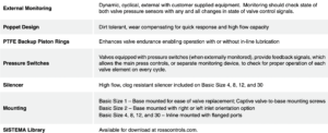
VALVE FEATURES
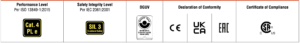
PRODUCT CREDENTIALS
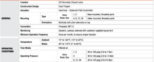
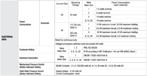
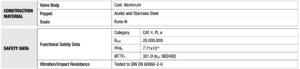
Specifications
Ordering Information
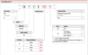
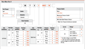
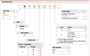
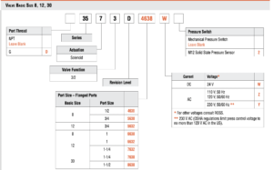
MODEL NUMBER CONFIGURATOR(3-Way 2-Position Valves)
Pressure Switches & Monitoring
Valves without pressure switches must not be used to control clutch/brake mechanisms on press machinery.
Valves with pressure switches must be used in conjunction with an external monitoring device to assist with OSHA compliance (Ref. 1910.217).
The valves on this page do not have a built-in monitor, and so must only be used in conjunction with an external monitoring system. Such monitoring system must be capable of inhibiting the operation of the valve and associated machinery in the event of a failure within the valve.
CAUTION: If the system must be reset, electrical signals to both solenoids must be removed to prevent the machine from immediately recycling and producing a potentially hazardous condition.
Valve Operation
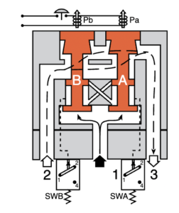
| Conditions at Start | Inlet 1 is closed to outlet 2 by both valve elements A and B. Outlet 2 is open to exhaust 3. Pressure signals at both switches SWA and SWB are exhausted. Contacts 1 and 2 of switches SWA and SWB are connected. |
 | |
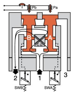
| Normal Operation | Simultaneously energizing both solenoids actuates both pilots and causes valve elements A and B to shift. Inlet 1 is then connected to outlet 2 via crossflow passages C and D. Exhaust 3 is closed. Sensing pressure signals go to each pressure switch and become equal to inlet pressure. Both switches trip and now contacts 1 and 4 of switches SWA and SWB are connected instead of contacts 1 and 2. |
 | |
| Completion of Normal Cycle | Simultaneously de-energizing both solenoids returns the valve to the “Conditions at Start” described above. |
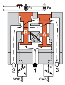
| Detecting a Malfunction | A malfunction in the system or the valve itself could cause one valve element to be open and the other closed. Air then flows past the inlet poppet on valve element A, into crossflow passage D, but is substantially blocked by the spool portion of element B. The large size of the open exhaust passage past element B keeps the pressure at the outlet port below 2 % of inlet pressure. Full sensing air pressure from side A goes to switch SWA, and a reduced pressure goes to switch SWB. This full pressure signal causes switch SWA to trip. Switch SWB, with a reduced pressure signal, does not trip. An external monitoring system can detect the malfunction by monitoring the condition of the switches SWA and SWB. The external monitoring system may then react accordingly by shutting down the power to the valve solenoids and any other components deemed necessary to stop the machine. |
 | |
| CAUTION | If the system must be reset, electrical signals to both solenoids must be removed to prevent the machine from immediately recycling and producing a potentially hazardous condition. |
Valve Technical Dat
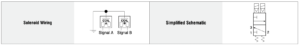
| Valve Schematic |
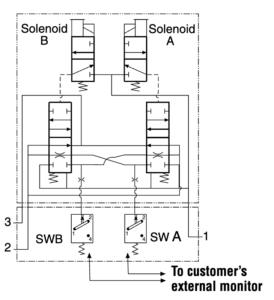 |
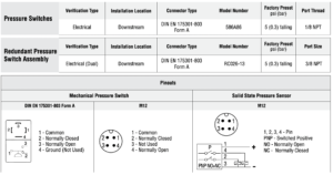
| Valve Solenoid & Pressure Switch Pinouts | ||
| Solenoid | DIN EN 175301-803 | |
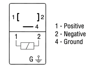 | ||
| Pressure Switch | DIN EN 175301-803 | M12 |
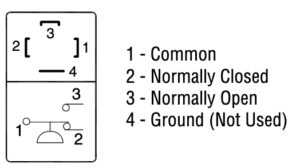 | 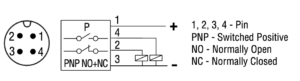 | |
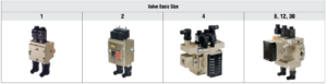
Valve Basic Size 1
| Dimensions-Inches(mm) | |
Valve without Pressure Switches | 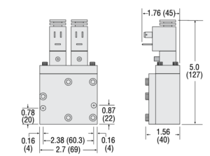 |
Valve with Pressure Switches | 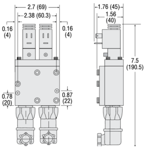 |
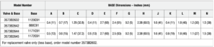
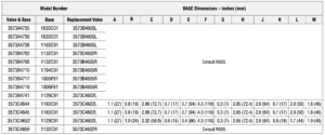
| Base | 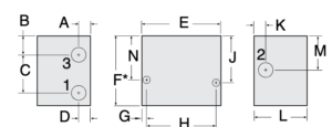 |
Valve Basic Size 2
| Dimensions-Inches(mm) | |
Valve without Pressure Switches | 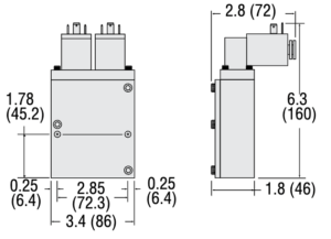 |
Valve with Pressure Switches | 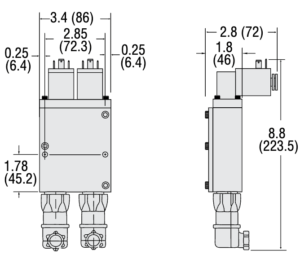 |
| Base | 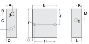 |
Valve Basic Size 4, 8, 12, 30
| Dimensions-Inches(mm) | |
| Basic Size 4 | 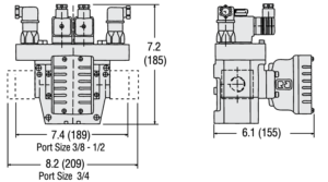 |
| Basic Size 8 | 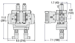 |
| Basic Size 12 | 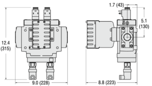 |
| Basic Size 30 | 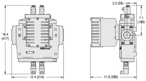 |
Accessories
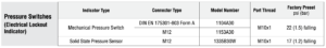
ELECTRICAL STATUS INDICATION
ENERGY RELEASE VERIFICATION
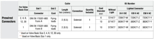
PREWIRED ELECTRICAL CONNECTORS
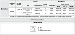
ELECTRICAL CONNECTORS
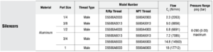
EXHAUST SILENCERS
RESET VALVES FOR DOUBLE VALVES WITH REMOTE RESET
Valves with the remote reset option require a small 3/2 reset valve and the installation of a 1/8 inch air line from the reset valve to the reset port of the double valve. ROSS offers 3/2 normally closed valves with either manual or electric control that are suitable for this purpose.
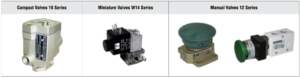
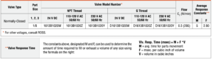
Direct Solenoid Pilot Control – Compact Valves 16 Series for Line Mounting
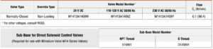
Direct Solenoid Pilot Control – Miniature Valve W14 Series for Base Mounting
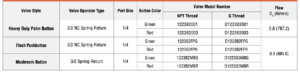
Manual Palm Button Valves 12 Series
Related Products
-
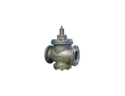
YOSHITAKE GP-1000AS Pressure Reducing Valve – Steam
-
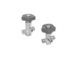
Chiyoda Seiki SV-30-TA1 Neck Valve/Purge Valve
-
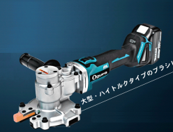
Ogura HSC-20BLN Cordless Tip Saw Cutter
-
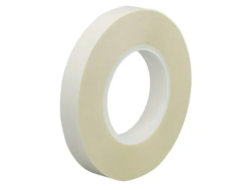
TERAOKA SEISAKUSHO7641W #25 Transparent Double-coated Adhesive Film Tape
-
PET-2000 Automatic Aluminum Vane Eddy Current Flaw Detector for Automotive Air Conditioners
-
YOSHITAKE AL-150TML Safety and Relief Valve
REQUEST QUOTATION

PAYMENT

LINK


